Astable 555 Timer Schematic - Schematic Circuit Diagram Astable Multivibrator using 555 ... - If you want to know all the pinout of the 555 timer, what each pin is and what each pin does, see 555 timer pinout.
Astable 555 Timer Schematic - Schematic Circuit Diagram Astable Multivibrator using 555 ... - If you want to know all the pinout of the 555 timer, what each pin is and what each pin does, see 555 timer pinout.. The 555 timer is a chip that can be us… Features of 555 timer ic. This 555 timer circuit will remain in either state indefinitely and is therefore bistable. The internal block diagram and schematic of the 555 timer are highlighted with the same color across all three drawings to clarify how the chip is implemented: If you want to know all the pinout of the 555 timer, what each pin is and what each pin does, see 555 timer pinout.
For example, it can also generate frequencies to produce sound when the output is connected to a. The modulating signal is applied at the pin 5 of the first ic 555 that is operating in astable mode. Many times when you see a project with flashing leds, it's a 555 timer at work. Apr 07, 2021 · in order to achieve pulse position modulation, two 555 timer ic's are used in which one operates in astable mode and the other in monostable mode. Astable mode, monostable mode and bistable mode are the three modes of operation of ic 555.
Rain Alarm using 555 Timer - Hobby Circuit from electrosome.com For example, it can also generate frequencies to produce sound when the output is connected to a. This 555 timer circuit will remain in either state indefinitely and is therefore bistable. The modulating signal is applied at the pin 5 of the first ic 555 that is operating in astable mode. The threshold input (pin 6) is connected to ground to ensure that it cannot reset the bistable circuit as it would in a normal timing application. But it has a lot of other interesting applications too. Apr 07, 2021 · in order to achieve pulse position modulation, two 555 timer ic's are used in which one operates in astable mode and the other in monostable mode. Then the bistable 555 timer is stable in both states, "high" and "low". The internal block diagram and schematic of the 555 timer are highlighted with the same color across all three drawings to clarify how the chip is implemented:
The 555 timer can be obtained very cheaply from pretty much any electronic retailer.
The modulating signal is applied at the pin 5 of the first ic 555 that is operating in astable mode. Dec 07, 2018 · 555 timer ic. Many times when you see a project with flashing leds, it's a 555 timer at work. Astable mode, monostable mode and bistable mode are the three modes of operation of ic 555. Features of 555 timer ic. Then the bistable 555 timer is stable in both states, "high" and "low". This 555 timer circuit will remain in either state indefinitely and is therefore bistable. The astable mode is what most people think of when it comes to the 555 timer. This tutorial provides sample circuits to set up a 555 timer in monostable, astable, and bistable modes as well as an in depth discussion of how the 555 timer works and how to choose components to use with it. The 555 timer can be obtained very cheaply from pretty much any electronic retailer. The output of this ic 555 is a pulse width modulated wave. If you want to know all the pinout of the 555 timer, what each pin is and what each pin does, see 555 timer pinout. For example, it can also generate frequencies to produce sound when the output is connected to a.
The 555 timer is a chip that can be us… I'm trying to build a 555 timer circuit that has an output low time of 5 minutes and an output high time of 250. For example, it can also generate frequencies to produce sound when the output is connected to a. Many times when you see a project with flashing leds, it's a 555 timer at work. Jul 02, 2020 · astable mode of the 555 timer.
IC Timer 555 Astable Multivibrator 50% Duty cycle ... from i.stack.imgur.com Astable mode, monostable mode and bistable mode are the three modes of operation of ic 555. Ic 555 timer ic is one of the most popular integrated circuit chip used for a variety of applications such as astable, monostable, bistable multivibrators, timer circuits, oscillators, pwm (pulse width modulation), ppm (pulse position modulation), square wave generator or pulse generator, etc. The 555 timer can be obtained very cheaply from pretty much any electronic retailer. The threshold input (pin 6) is connected to ground to ensure that it cannot reset the bistable circuit as it would in a normal timing application. For example, it can also generate frequencies to produce sound when the output is connected to a. Features of 555 timer ic. Jul 02, 2020 · astable mode of the 555 timer. But it has a lot of other interesting applications too.
I'm trying to build a 555 timer circuit that has an output low time of 5 minutes and an output high time of 250.
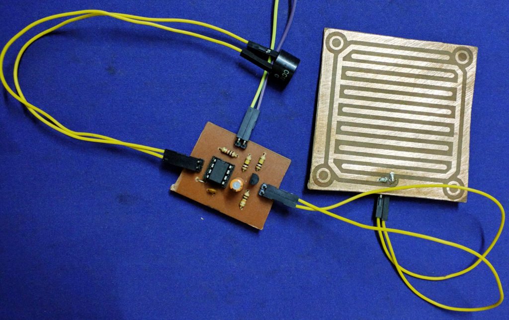
The threshold input (pin 6) is connected to ground to ensure that it cannot reset the bistable circuit as it would in a normal timing application. In this circuit, we will connect the 555 timer to be in astable mode. The modulating signal is applied at the pin 5 of the first ic 555 that is operating in astable mode. But it has a lot of other interesting applications too. The astable mode is what most people think of when it comes to the 555 timer. The internal block diagram and schematic of the 555 timer are highlighted with the same color across all three drawings to clarify how the chip is implemented: Then the bistable 555 timer is stable in both states, "high" and "low". For example, it can also generate frequencies to produce sound when the output is connected to a. Apr 07, 2021 · in order to achieve pulse position modulation, two 555 timer ic's are used in which one operates in astable mode and the other in monostable mode. This 555 timer circuit will remain in either state indefinitely and is therefore bistable. The 555 timer is a chip that can be us… Astable mode, monostable mode and bistable mode are the three modes of operation of ic 555. The timer ic is set up to work in either of the two modes.
I'm trying to build a 555 timer circuit that has an output low time of 5 minutes and an output high time of 250. But it has a lot of other interesting applications too. If you want to know all the pinout of the 555 timer, what each pin is and what each pin does, see 555 timer pinout. For example, it can also generate frequencies to produce sound when the output is connected to a. This 555 timer circuit will remain in either state indefinitely and is therefore bistable.
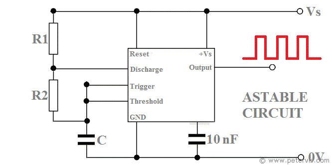
555 Timer ASTABLE Circuit and Equations from www.petervis.com Ic 555 timer ic is one of the most popular integrated circuit chip used for a variety of applications such as astable, monostable, bistable multivibrators, timer circuits, oscillators, pwm (pulse width modulation), ppm (pulse position modulation), square wave generator or pulse generator, etc. The modulating signal is applied at the pin 5 of the first ic 555 that is operating in astable mode. This 555 timer circuit will remain in either state indefinitely and is therefore bistable. I'm trying to build a 555 timer circuit that has an output low time of 5 minutes and an output high time of 250. But it has a lot of other interesting applications too. Features of 555 timer ic. Astable mode, monostable mode and bistable mode are the three modes of operation of ic 555. Between the positive supply voltage v cc and the ground gnd is a voltage divider consisting of three identical resistors, which create two reference voltages at 1 ⁄ 3 v cc and 2.
I'm trying to build a 555 timer circuit that has an output low time of 5 minutes and an output high time of 250.
The internal block diagram and schematic of the 555 timer are highlighted with the same color across all three drawings to clarify how the chip is implemented: The 555 timer can be obtained very cheaply from pretty much any electronic retailer. I'm trying to build a 555 timer circuit that has an output low time of 5 minutes and an output high time of 250. If you want to know all the pinout of the 555 timer, what each pin is and what each pin does, see 555 timer pinout. Many times when you see a project with flashing leds, it's a 555 timer at work. Dec 07, 2018 · 555 timer ic. Features of 555 timer ic. Apr 07, 2021 · in order to achieve pulse position modulation, two 555 timer ic's are used in which one operates in astable mode and the other in monostable mode. The threshold input (pin 6) is connected to ground to ensure that it cannot reset the bistable circuit as it would in a normal timing application. For example, it can also generate frequencies to produce sound when the output is connected to a. The 555 timer is a chip that can be us… Between the positive supply voltage v cc and the ground gnd is a voltage divider consisting of three identical resistors, which create two reference voltages at 1 ⁄ 3 v cc and 2. The astable mode is what most people think of when it comes to the 555 timer.
Dec 07, 2018 · 555 timer ic 555 timer schematic. Ic 555 timer ic is one of the most popular integrated circuit chip used for a variety of applications such as astable, monostable, bistable multivibrators, timer circuits, oscillators, pwm (pulse width modulation), ppm (pulse position modulation), square wave generator or pulse generator, etc.


0 Komentar